C-200AIR-High Pressure Water Blasters
E-Shop
QG65N2-KDXYh-090H-AV3-AI@UL
|
General specifications 14308, v20241017 |
|
| Housing | Reinforced plastic injection molded (Faradex DS, black, EMI shielded by stainless steel fiber in PC) |
| Dimensions (indicative) | 60x50x27 mm |
| Mounting | Not included: M5 pan head screws. Mounting on flat surface only. Screw with care |
| Ingress Protection (IEC 60529) | IP67, IP69K (with IP69K mating connector) |
| Relative humidity | 0 – 95% (non condensing, housing fully potted) |
| Weight | approx. 110 gram |
| Supply voltage | 12- 32 V dc |
| Polarity protection | Yes |
| Current consumption | ≤ 25 mA |
| Operating temperature | -40 .. +80 °C |
| Storage temperature | -40 .. +85 °C |
| Measuring range | Factory defaults: ± 90° |
| Centering function | Yes (5 V = 0°), range: ±5° |
| Frequency response (-3dB) | 0 – 10 Hz |
| Accuracy (overall @20°C) | 0,1° typ. |
| Offset error | ± 0,05° typ. (± 0.1° 2σ) after zero adjustment |
| Non linearity | ± 0,08° typ., ± 0,15° 2σ, ± 0,2° max. |
| Sensitivity error | not applicable. Repeatability 0,05° |
| Resolution | 0,01° |
| Temperature coefficient | ±0,3° typ., ±0,5° 2 sigma (over full temperature range) |
| Max mechanical shock | 10,000g (max 0,2ms, non-repetitive) |
| Output | 0 – 10 V |
| Output load | Rload ≥20kΩ, Cload ≤20 nF |
| Short circuit protection | Yes |
| Output refresh rate | 10 ms |
| Programming options | Factory programmable (measuring range, filtering) |
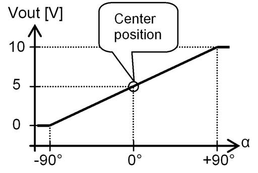
| Transfer characteristic | |
| Uout = 5 + 5*(α/90) [V]
clipping outside measuring range
Zero adjustment: eliminate mech. offsets Connect zero adjustment input to ground (>0,5sec) within 1 min. after power up. Normally this input should be left unconnected or permanent connected to Gnd
|
 |
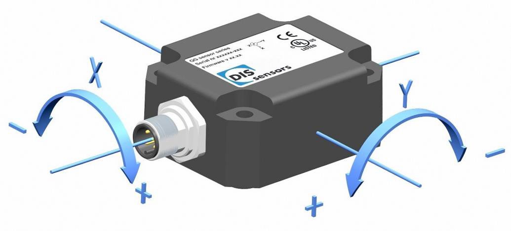
| Measurement orientation | |
|
Default 0°: horizontal (label upwards), no acceleration applied.
Cross tilt sensitivity error: < (0,12 * cross tilt angle)² % typ.
→ one axis <10° tilt for max. accuracy → only one axis may exceed 45° tilt
|
 |
| Connectivity (cable length ±10%) | |||
|
Connection
|
M12 male 5p A-coding connector (Brass Nickel coated, contacts copper alloy) | ||
| Wire / pin coding
|
Pin 1: | + Supply voltage | 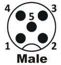 |
| Pin 2: | Output Y | ||
| Pin 3: | Gnd | ||
| Pin 4: | Output X | ||
| Pin 5: | Zero adjustment input | ||
|
Mechanical dimensions (indicative only) |
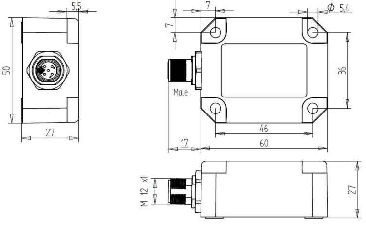 |